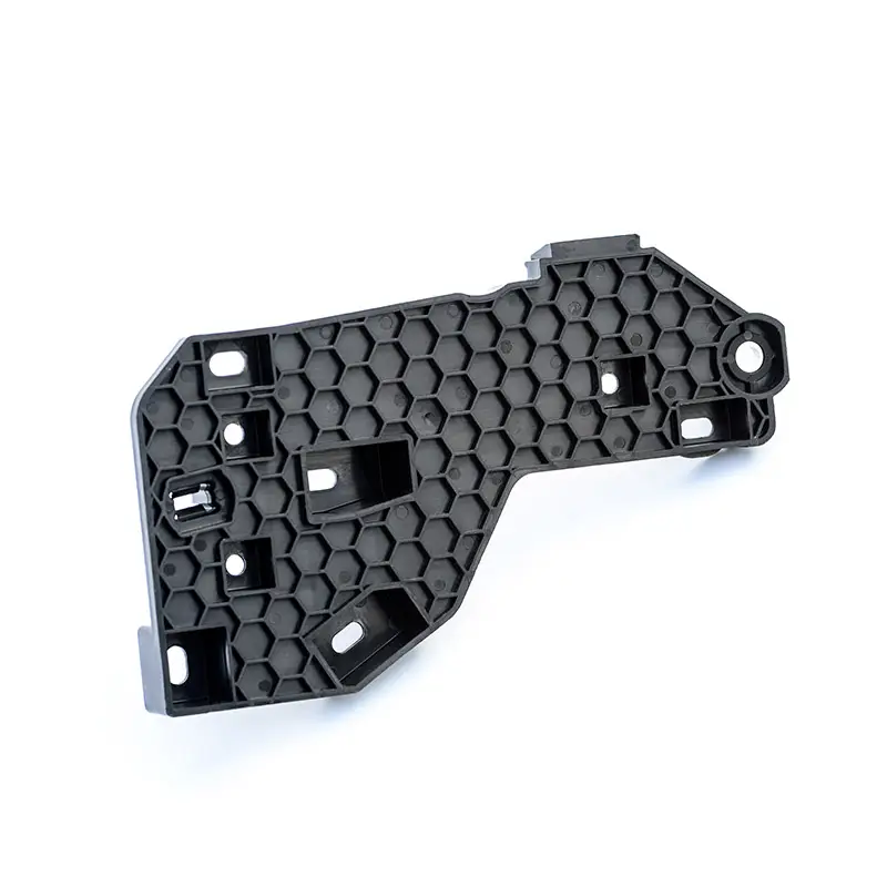
A CAD model can confirm geometry, but it cannot fully reveal how a plastic part will behave after injection molding. Issues involving filling, ejection, warpage, assembly fit, surface appearance, and material behavior often become clearer only after physical parts are produced. Rapid prototype tooling addresses this gap by creating a mold quickly enough for engineering teams to test representative injection-molded components before committing to full production tooling.
The value therefore lies less in making a mold quickly than in obtaining useful evidence early. A well-planned prototype tool should match the project’s testing objective, expected quantity, resin, geometry, and likely production direction.
Why Prototype Tooling Becomes Necessary After CAD Validation
Early prototypes made through machining or additive manufacturing can answer important questions about dimensions and form. They may not reproduce the behavior of an injection-molded component, particularly when the final product depends on molded wall sections, ribs, bosses, draft, gates, or production-grade thermoplastics.
HordRT‘s prototype tooling service describes molded prototypes as a way to evaluate geometry, material performance, assembly fit, and functional behavior under more representative manufacturing conditions. Its current service information lists aluminum, soft-steel, shared MUD inserts, and different cavity configurations as tooling options.
That distinction matters during design freezes. A component that fits correctly as a machined sample may still expose molding-related issues once the actual resin and process are introduced. Detecting those issues before a higher-volume mold is finalized can prevent expensive downstream modifications.
How the Tooling Route Shapes the Prototype
Tool selection should follow the question the prototype needs to answer. If engineers primarily need rapid design verification and a limited number of molded parts, aluminum tooling can be appropriate. HordRT’s published information identifies aluminum prototype molds as a fast-machined option for design verification, functional testing, and limited production.
Greater durability may justify steel construction. The company’s prototype tooling information associates soft-steel tooling with more demanding materials, tighter tolerances, and higher quantities. Shared MUD mold inserts provide another route, using interchangeable cavity and core inserts within a reusable mold base to reduce tooling investment and simplify setup.
Cavity count is similarly tied to purpose. A single cavity may be sufficient for engineering validation, while multiple cavities can become relevant when teams need more samples or want to investigate production-oriented output. The objective should determine the configuration rather than an assumption that a larger tool is automatically better.
What Happens Between CAD Approval and T0 Samples
A productive tooling workflow begins before metal reaches the machine. HordRT’s published rapid-prototyping process starts with design-for-manufacturability analysis covering items such as parting lines, gate locations, ejector positions, wall thickness, tolerances, and potential molding defects.
Once the tooling strategy is established, inserts and mold components can be machined using processes such as CNC machining, EDM, wire cutting, and drilling. Components are then fitted, polished where required, assembled, and prepared for the first molding trial.
The T0 trial is more than a sample-production milestone. It creates an opportunity to compare actual molded parts against the intended design. Filling behavior, ejection, dimensions, appearance, and functional interfaces can be reviewed before further changes are made.
A published HordRT case study illustrates this workflow with a TPO component produced using a hard-aluminum insert and shared standard mold base, with a reported seven-day lead time. The case also describes DFM review before tooling manufacture and engineering changes after initial samples.
Choosing Tool Construction Around the Validation Goal
Material selection deserves the same attention as mold construction. Prototype tooling is most informative when the molded parts use the resin intended for subsequent evaluation. HordRT’s current prototype tooling information lists production-grade materials including ABS, PP, PC, PC/ABS, PA, POM, PBT, PMMA, TPE, TPU, and selected reinforced or flame-retardant grades.
That becomes particularly relevant for functional testing. Mechanical strength, stiffness, impact response, dimensional stability, surface appearance, and assembly behavior can depend substantially on the chosen polymer. Substituting a materially different resin may make the prototype faster to produce but less representative of the eventual product.
Tool life should also be specified around the project rather than treated as a universal number. Published HordRT information states that prototype mold life depends on factors including tool material, geometry, resin, and operating conditions. Its case-study material reports typical prototype-tooling life ranges and identifies longer life for certain steel selections.
Using Prototype Results to Decide the Production Path
The strongest outcome of prototype tooling is not simply a box of finished samples. It is a better-informed production decision. If the T0 parts reveal a gate-related appearance issue, difficult ejection, insufficient draft, dimensional deviation, or assembly interference, engineers can address the underlying design or tooling condition before scaling the project.
HordRT states that prototype tools can accommodate modifications during validation, although the feasibility and cost depend on the specific change and mold structure.
A successful validation can then provide a clearer basis for production-tooling design. Decisions about cavity quantity, mold steel, cooling strategy, automation, and long-term tool life can be made with physical evidence rather than relying entirely on assumptions from the original CAD model.
For B2B product teams, that makes rapid prototype tooling a development-control method rather than merely a faster mold-making service. Its purpose is to move critical manufacturing questions forward while changes are still manageable.
The most effective projects begin by defining what must be proven, selecting the tool around that objective, and using the first molded parts as engineering evidence. Done correctly, prototype tooling creates a controlled transition between design intent and production reality—reducing uncertainty before the investment in full-scale manufacturing becomes much larger.
